

This is an EL34 Class A Tube amp, maximum output is 6w RMS per channel. So you need super sensitive speakers to enjoy this amp.
Problem is by default I measured about 20% THD of distortion in it’s default configuration.

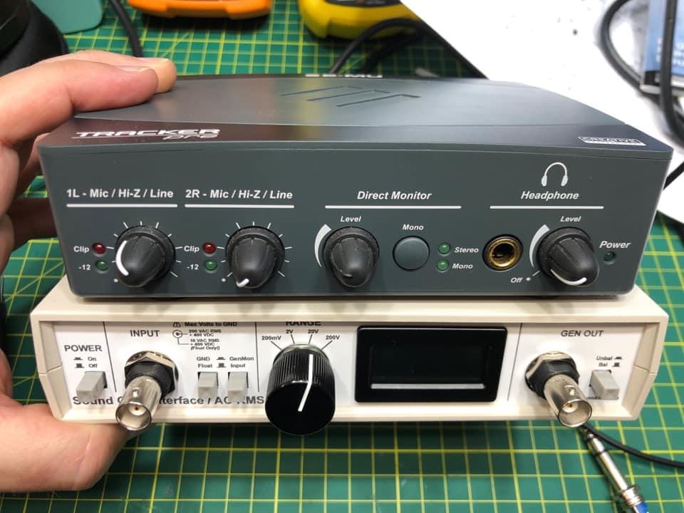
Here is what I use to take my THD readings, it comprises of a Windows PC running ARTA Software, A high quality USB Sounds card, in my case a Creative Labs Tracker-Pre USB 2, and a kit that I made called a Sounds card Interface. The Creative Labs Tracker-Pre USB 2 is no longer available. It is a very ultra-low noise Class-A device. See the input specs below. The Sound card interface is a build it yourself kit. I’ll post a seperate article on it as I have a lot to say about it.
Creative Labs Tracker-Pre USB 2:
- Type: E-MU CurrentMorph combo mic preamp and Hi-Z/line input
- A/D converter: AK5385
- Max level: +6.4dBV bal/unbal (+6.9 dBu), Hi-Z/line balanced input: +6.9dBV bal/unbal (+9.1dBu), Microphone Preamplifier: +6.4dBV bal/unbal (+8.6dBu)
- Frequency response (min gain, 20Hz-20kHz): +0.0/-0.03dB
- Dynamic range (A-weighted, 1kHz, min gain): 112dB
- Signal-to-Noise ratio (A-weighted, min gain): 112dB
- THD+N (1kHz at – 1dBFS, min gain): -102dB (.0007%)
- EIN (20Hz-20kHz, 150ohm, unweighted): -127dBu
- Input impedance: Hi-Z/line balanced input: 1Mohm, microphone preamplifier: 1.5Kohms
So, I decided to try to change the Cathode EL34 Tube current. I measured it at 46mA with the default circuit values and of course observing a huge amount of THD ~20% at 6w RMS output.


According to my calculations, for Class A operation I should be using Maximum Plate dissipation of 25w (EL34) Divided by the Plate voltage, I measured that at 330v when loaded. Hope I was measuring from the correct spot 🙂
Maximum Plate Dissipation [W] / Plate voltage [V] = Current [A]
So 25/330= 0.075 -> 75mA

So these Final Tubes were effectively not running fully saturated. So it’s looking like 75mA “should” be the sweet spot for the Cathode Current.
You have to change the bias cathode resistor to a larger value for less bias current (more bias voltage) and a smaller value for more bias current (less bias voltage).
The original Bias resister was 6w 500 Ohm.
I attached a 3w Linear 1k Pot to the same position. This also allowed me to fully adjust the Bias. While watching to DSO and the THD graph. So I tried ~220 Ohm by pre-setting the pot to 220 Ohm, I could then see 75mA current on the Cathode.
BINGO !! Now I could instantly see the THD drop by ~68% 🙂 from ~19% at full power down to ~6%.
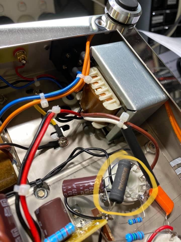
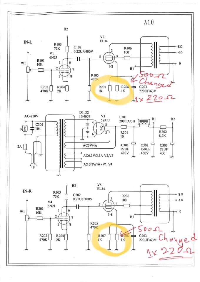
You can see below in the A10’s Circuit diagram, they used 2 x 1K Ohm resistors in parallel. The unit I have just has 1 x 500 Ohm 6w. You can see below in my case I ended up using 1 x 220 Ohm 5w ceramic Resistor.

So now at 7v RMS out into 8 Ohm load, 7sq/8= 6.125w RMS output, this is the maximum I can expect out of this amp. When doing this the Plate voltage dropped to 330v when it was around 350v with running 46mA Bias.
So pretty happy with that so far, next steps will be to try some negative feedback. To see if I can get even lower results but also see how much power I lose on the output in doing so. Because negative feedback is the process of taking some amplifier output and feeding it back to a preceding stage 180 degrees out of Phase. So you lose some output power. But that’s for after xmas, need to go and get some more bits to do that.
Question is where should a push back the negative feedback to the EL34 or 6n2 ? I would assume the 6n2. As I’m using 2K for the Bias of the 6n2 then I would need to use maybe 3K resister in line with the feedback loop as a starting point, might use a 5K linear pot and have a play. That’s is for now, sorry for the long essay, but I’ll use this as a future reference 🙂
I’ll also post a 3 min video of my trying all the above. Sometimes a demo is better than reading someone’s description.
