So being a fan of making and repairing Audio Amplifiers, I decided to make a proper Non-Inductive Resistive Dummy load.
First step was to find some decent resistors, so after a lot of looking around I found these nice T-220 form factor devices.
Caddock MP850-2.00-1% Non-Inductive T-220 package resistors.
The MP850 Kool-Tab® Power Film Resistors are constructed with Caddock’s Micronox resistance film fired onto a flat ceramic substrate which is thermally bonded to the copper heat sink tab. The resistor body is then molded with a high temperature molding compound to finish the metal tab TO-220 package. The lead wire attachment and resistance element geometry are configured to provide outstanding non-inductive performance.
https://au.mouser.com/datasheet/2/62/MP800_Series-2189.pdf
I selected the 50w 2 Ohm 1% versions as I wanted to make an 8 Ohm – 4 Ohm switchable load.
• 50 Watts at +25°C Case Temperature derated to zero at +150°C.
• Copper Heat Sink Integral in the Molded Package.
• Resistance Range of 0.20 ohm to 10.0 K.
• Resistor element is electrically isolated from the mounting surface.
• Non-inductive Design.
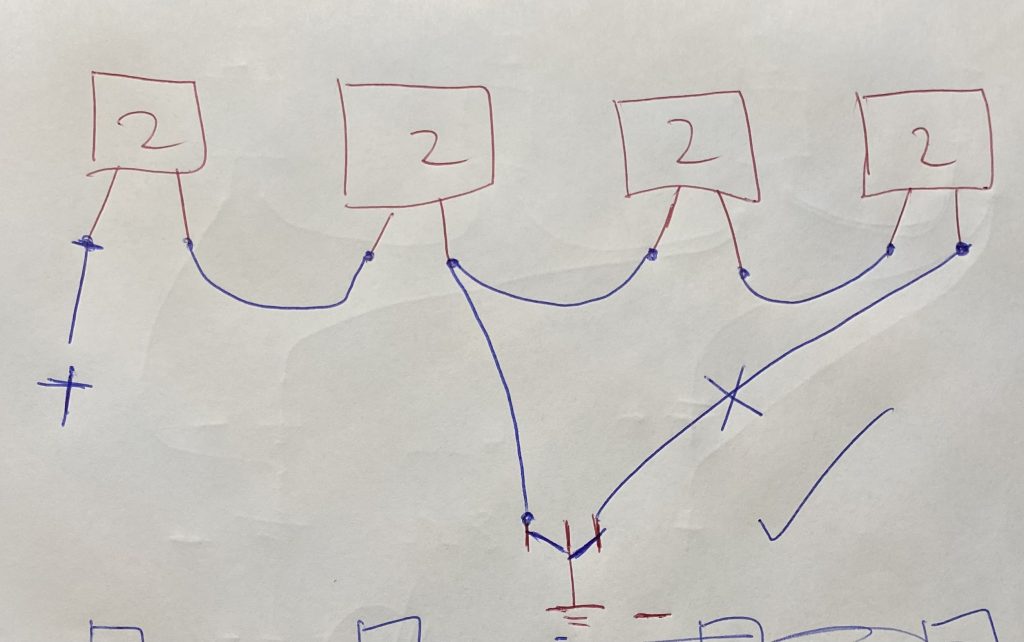
These are quite expensive so by Selecting the 2 Ohm 50w variant I was able to make a load of 8 Ohm and 4 Ohm switchable.
So the simplest way to get this done is to wire these up in series per channel. My rough sketch below, with a SPDT switch to switch between 8 & 4 Ohms. Obviously in 4 Ohm mode it would halve the wattage, but 100w is plenty for my applications. So I would need 8 x MP850 @ 2 Ohm’s each.
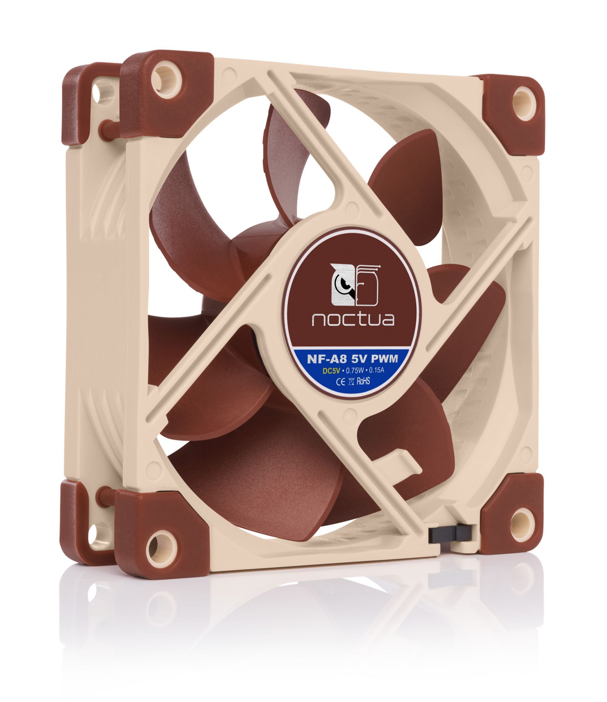
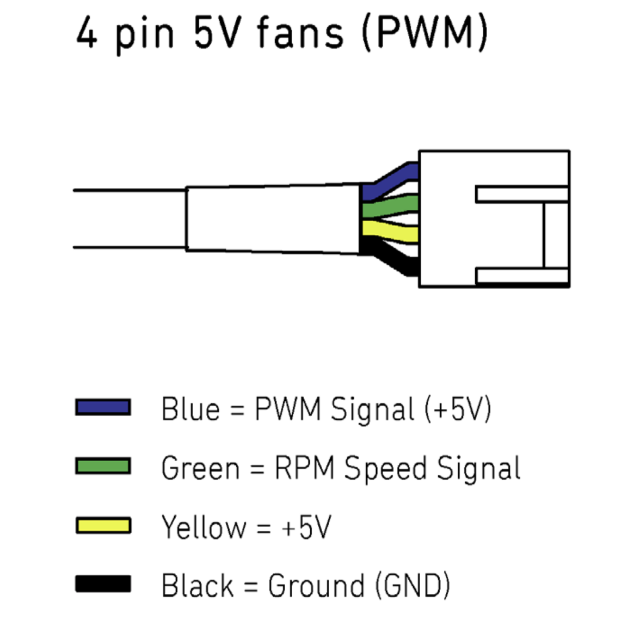
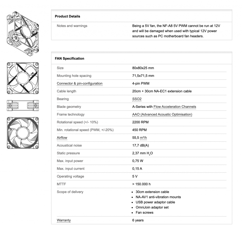
Next step was to find a Fan and heatsinks for this project. I decided I wanted to Fan cool this guy. So I selected a Noctua 5v PWM controlled Fan for this project. As I wanted this thing to be super quiet and only run the fan when required. I ended up using the Noctua NF-A8 5v PWM 4 Pin 80mm FAN. Max RPM of 2200 and runs directly from 5v so I can run the Fan and the controlling Arduino Nano from the same PSU voltage rail. I didn’t really want to get into building some voltage rectifiers. So it just simplifies the whole thing.
https://noctua.at/en/products/fan/nf-a8-5v-pwm
Ok Next step was to BreadBoard a mock up of this control system for the Fam. I decided to use an Arduino Nano v3 as I have heaps of these laying around and they cost peanuts from AliExpress 🙂
Next step was to work out what I wanted to use as a HeatSink Temp sensor, Something that I could easily attach to the Heatsinks and was accurate. The Dallas Semi DS18b20 was my choice. As it’s an i2C bus temp sensor and I had heaps laying around too 🙂
https://datasheets.maximintegrated.com/en/ds/DS18B20.pdf
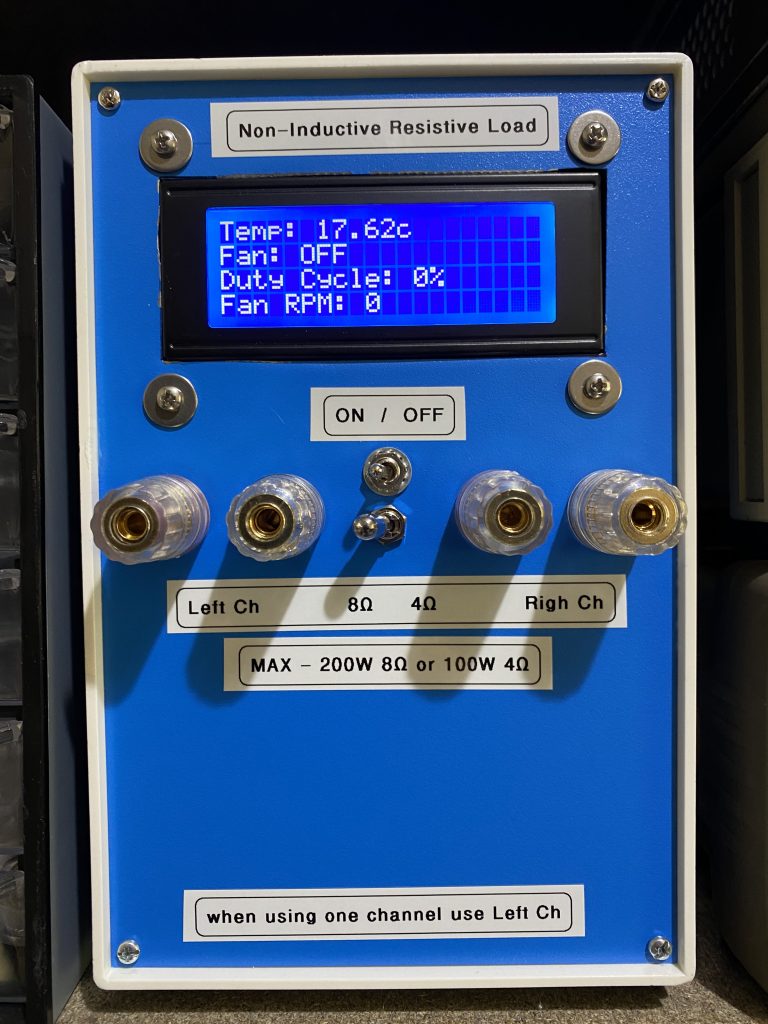
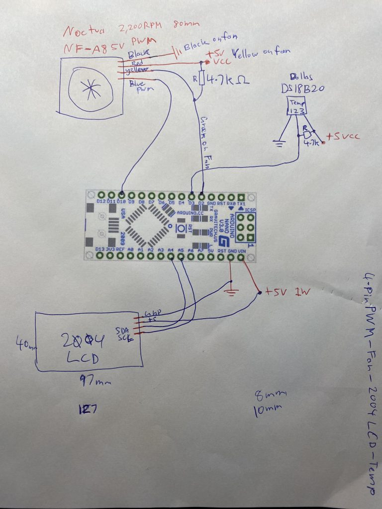
So here is what I ended up with:
- Arduino Nano v3
- Arduino Nano v3 shield with screw terminals, just easier to work with and make future tweaks and changes if required.
- Noctua NF-A8 5v PWM 4-pin Fan
- Dallas Semi DS18B20 as the Temp Sensor
- 2004 Blue LCD with an i2C piggy back controller
- 5v Power (Going to just use an external PowerPack)
Below is a the wiring diagram I ended up with on my Breadboard.
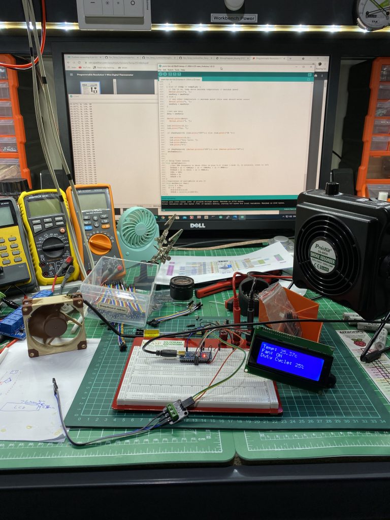
Here is my Breadboard mock up ready to code the Nano with what I wanted it to do.
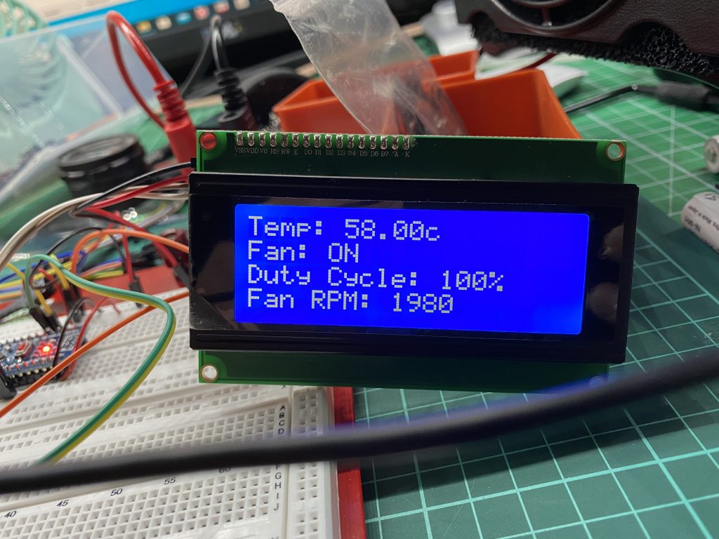
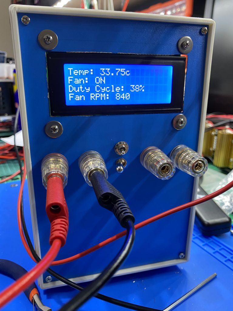
I wanted to show Temp, Fan status, Fan Duty Cycle and RPM, may as well make use of all 4 LCD lines 😉
Got the RPM working now and set up the Fan to turn on at a certain Temp and run at 100% duty cycle at 50Deg C. ~2000-2200 RPM for this fan.
Next step was to find a Fan Assisted heatsink for my 80mm Fan, Found these at Jaycar, two of them interlock to make an 80mm Fan cooling tunnel.
Will add Arduino Code here shortly
// Dummy Load Fan Temp Control.ino ##############################################
/* This code was written to control the temperature of a Dummy Load
by measuring the temperature with a DS18b20 Temperature probe and
outputting a PWM signal with the Arduino Nano to control a 4-Pin fan.
It will also switch off fan when cool threshold is reached */

/*
The following constants should be changed according to the use case:
constant (default value) - description
tempLow (25) - Below this temperature (minus half hysteresis) the fan shuts off.
               It turns on again at this temperature plus half hysteresis
tempHigh (50) - At and above this temperature the fan is at maximum speed
hyteresis (5) - Hysteresis to prevent frequent on/off switching at the threshold
minDuty (10) - Minimum fan speed to prevent stalling
maxDuty (100) - Maximum fan speed to limit noise
 */


#include <OneWire.h>
#include <DallasTemperature.h>
#include <LiquidCrystal_I2C.h>

// Digital pin of temperature sensor
#define ONE_WIRE_BUS 3

// Setup a oneWire instance
OneWire oneWire(ONE_WIRE_BUS);

// Setup temperature sensor library
DallasTemperature sensors(&oneWire);

// define LCD type
LiquidCrystal_I2C lcd(0x27, 20, 4);

// PWM output pin
const byte OC1B_PIN = 10;

// how frequently the main loop runs
const int tempSetInterval = 1000;

// **** RPM Varibles used for calculations
int NbTopsFan; int Calc;

//The pin location of the sensor
int hallsensor = 2; typedef struct{

//Defines the structure for multiple fans and
//their dividers
char fantype;
unsigned int fandiv; }fanspec;

//Definitions of the fans
//This is the varible used to select the fan and it's divider,
//set 1 for unipole hall effect sensor (Noctua is uniPole)
//and 2 for bipole hall effect sensor
fanspec fanspace[3]={{0,1},{1,2},{2,8}}; char fan = 1;

// temperatur settings
const float tempLow = 25;
const float tempHigh = 50;
const float hyteresis = 5;
const int minDuty = 10;
const int maxDuty = 100;

// state on/off of Fan
bool fanState = HIGH;

// current duty cycle
byte duty = 100;

// new duty cycle
byte newDuty = 100;

void rpm ()
// **** RPM This is the function that the interupt calls
{ NbTopsFan++; }

void setup() {
  //enable output for Timer 1
  pinMode(OC1B_PIN,OUTPUT);
  setupTimer1();

  // RPM
  pinMode(hallsensor, INPUT);
  attachInterrupt(0, rpm, RISING);

 // initialize the lcd
  lcd.init();
  lcd.init();
  lcd.backlight();
  lcd.setCursor(0,0);
  lcd.print("Dummy Load");
  lcd.setCursor(0,1);
  lcd.print("Controller v1.0");
  lcd.setCursor(0,2);
  lcd.print("by Mark Bedwani");
  delay(4000);
  lcd.init();


  // start serial port
  Serial.begin(9600);

  // Start up the temperature library
  sensors.begin();
  sensors.requestTemperatures();


  // welcome message
  Serial.println("## Start of Program ##");
  Serial.println("## By Mark Bedwani ##");
  Serial.println();

  Serial.println("# Connections #");

  Serial.println(" Temperature Sensor (VCC, Data, GND)");
  Serial.print(  "            Arduino: 3V3, D");
  Serial.print(ONE_WIRE_BUS);
  Serial.println("  , GND");
  Serial.println("            *add 4k7 pullup between VCC and Data");
  Serial.println();

  Serial.println(" 4-Pin Fan (GND, VCC, Sense, Control)");
  Serial.print(  "   Arduino: GND, 12V, n/C  , D");
  Serial.println(OC1B_PIN);
  Serial.println();

  Serial.println("# Settings #");
  Serial.println(" Below this temperature (minus half hysteresis) the fan");
  Serial.println(" shuts off. It enables again at this temperature plus half hysteresis:");
  Serial.print("  tempLow: "); Serial.print(tempLow); Serial.println("°C");


  Serial.println(" At and above this temperature the fan is at maximum speed: ");
  Serial.print("  tempHigh: "); Serial.print(tempHigh); Serial.println("°C");
  Serial.println();

  Serial.println(" Between these two temperatures the fan is regulated from");
  Serial.println(" the minimum fan speed to maximum fan speed");
  Serial.println();

  Serial.println(" Hysteresis to prevent frequent on/off switching at the threshold");
  Serial.print("  hyteresis: "); Serial.print(hyteresis); Serial.println("°C");
  Serial.println();

  Serial.println(" Minimum fan speed to prevent stalling");
  Serial.print("  minDuty: "); Serial.print(minDuty); Serial.println(" %");
  Serial.println();

  Serial.println(" Maximum fan speed to limit noise");
  Serial.print("  maxDuty: "); Serial.print(maxDuty); Serial.println(" %");
  Serial.println();

  Serial.println(" The fan speed is adjusted at the following interval:");
  Serial.print("  tempSetInterval: "); Serial.print(tempSetInterval); Serial.println(" ms");


  Serial.println(); delay(100);
  Serial.println(); delay(100);

  Serial.println("# Main Loop");
  Serial.println("(temperature, state, Duty Cycle, Fan On/Off)");
  Serial.println();

}


// main loop ##############################################
void loop() {
  // measure temperature, calculate Duty cycle, set PWM
  tempToPwmDuty();
  // wait for a bit
  delay(tempSetInterval);

  // **** RPM Set NbTops to 0 ready for calculations
  NbTopsFan = 0;

  //Enables interrupts
  sei();

  //Wait 1 second
  delay (1000);

  //Disable interrupts
  cli();

  //Times NbTopsFan (which is apprioxiamately the fequency the fan
  //is spinning at) by 60 seconds before dividing by the fan's divider
  Calc = ((NbTopsFan * 60)/fanspace[fan].fandiv);

  //Prints the number calculated above
  Serial.print (Calc, DEC);
  Serial.println (" rpm");
}


// setting PWM ############################################
void setPwmDuty() {
  if (duty == 0) {
    fanState = LOW;
  } else if (duty > 0) {
    fanState = HIGH;
  }

  setFan(duty);

}


// calculate new PWM ######################################
void tempToPwmDuty() {

  sensors.requestTemperatures();

  float temp = sensors.getTempCByIndex(0);

  Serial.print(temp);
  Serial.print("°C, ");

  lcd.setCursor(0,0);
  lcd.print("Temp: ");
  lcd.print(temp);
  lcd.print("c  ");

  if (temp < tempLow) {
    // distinguish two cases to consider hyteresis
    if (fanState == HIGH) {
      if (temp < tempLow - (hyteresis / 2) ) {
        // fan is on, temp below threshold minus hysteresis -> switch off
        Serial.print("a, ");
        newDuty = 0;
      } else {
        // fan is on, temp not below threshold minus hysteresis -> keep minimum speed
        Serial.print("b, ");
        newDuty = minDuty;
      }
    } else if (fanState == LOW) {
      // fan is off, temp below threshold -> keep off
      Serial.print("c, ");
      newDuty = 0;
    }

  } else if (temp < tempHigh) {
    // distinguish two cases to consider hyteresis
    if (fanState == HIGH) {
      // fan is on, temp above threshold > control fan speed
      Serial.print("d, ");
      newDuty = map(temp, tempLow, tempHigh, minDuty, maxDuty);
    } else if (fanState == LOW) {
      if (temp > tempLow + (hyteresis / 2) ) {
        // fan is off, temp above threshold plus hysteresis -> switch on
        Serial.print("e, ");
        newDuty = minDuty;
      } else {
        // fan is on, temp not above threshold plus hysteresis -> keep off
        Serial.print("f, ");
        newDuty = 0;
      }
    }
  } else if (temp >= tempHigh) {
    // fan is on, temp above maximum temperature -> maximum speed
    Serial.print("g, ");
    newDuty = maxDuty;
  } else {
    // any other temperature -> maximum speed (this case should never occur)
    Serial.print("h, ");
    newDuty = maxDuty;
  }

  //set new duty
  duty = newDuty;

  Serial.print(duty);
    Serial.print("%, ");

  lcd.setCursor(0,1);
  lcd.print("Fan: ");

  if (fanState==0) {lcd.print("OFF");} else {lcd.print("ON ");}

    lcd.setCursor(0,2);
    lcd.print("Duty Cycle: ");
    lcd.print(duty);
    lcd.print("%   ");
    lcd.setCursor(0,3);
    lcd.print ("Fan RPM: ");
    lcd.print (Calc, DEC);
    lcd.print ("      ");


  if (fanState==0) {Serial.println("OFF");} else {Serial.println("ON");}
  setPwmDuty();
}


// Setup Timer control
void setupTimer1(){
    //Set PWM frequency to about 25khz on pins 9,10 (timer 1 mode 10, no prescale, count to 320)
    TCCR1A = (1 << COM1A1) | (1 << COM1B1) | (1 << WGM11);
    TCCR1B = (1 << CS10) | (1 << WGM13);
    ICR1 = 320;
    OCR1A = 0;
    OCR1B = 0;
}
//equivalent of analogWrite on pin 10
void setFan(int fan){
  float f = fan;
  f = f / 100;
    f=f<0?0:f>1?1:f;
    OCR1B = (uint16_t)(320*f);
}

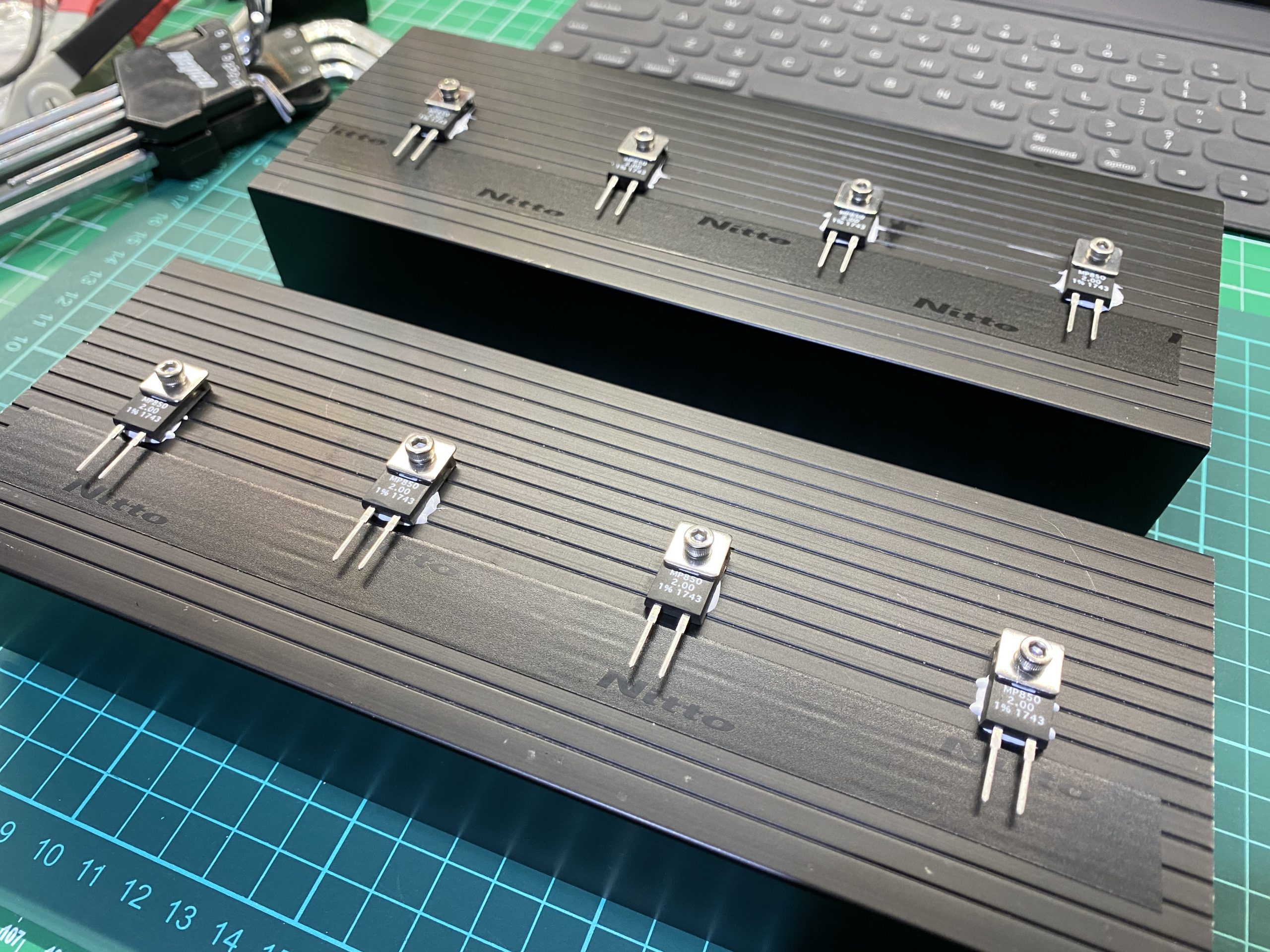
I drilled some holes for 4 on each side nicely spaced out and used a small amount of Heatsink compound. No needs to isolate these from the heatsink as Resistor element is electrically isolated from the mounting surface. I just added a nice run of Nitto Electrical tape near the pins, just to prevent a short to the heatsink if someone where to bend the pins at some point.
Next step was to find a case that would take these large heatsinks and Fan. Took ages me to fond something, in the end I found a cheap Chinese case on eBay. yes it cheap and flimsy but will do the job, this is not some nice kit that will be on display, it’s just a piece of test equipment.
270 x 140 x 210mm Metal Blue Project Junction Boxes Enclosure Case with Handle
About $46 inc. Shipping from HK to Sydney 🙂 can’t argue with that !!
https://www.ebay.com.au/itm/333593870559

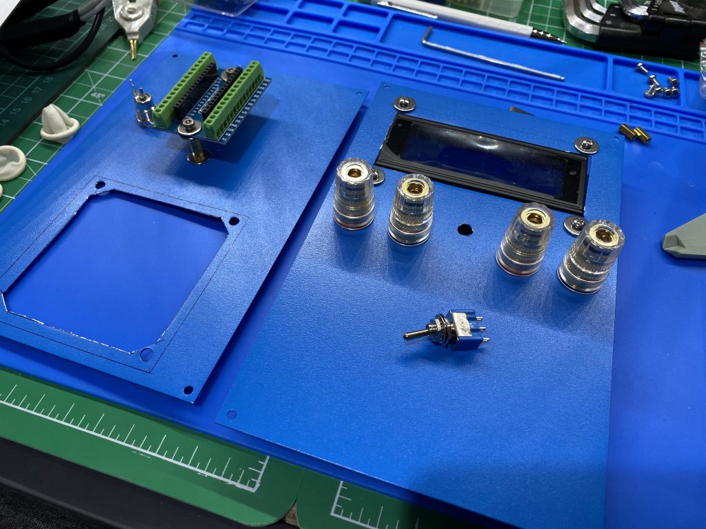
Rear cutout done and Nano Shield mounted. Also 5.5mm DC input jack for the 5v PSU. Front Right and Left terminals mounted. Power Switch and DPDT Resistance switch to be mounted.
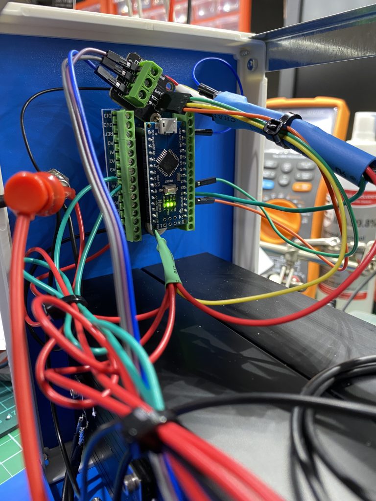
Just fits into chassis and mounted the Nano v3 to the upper rear plate.
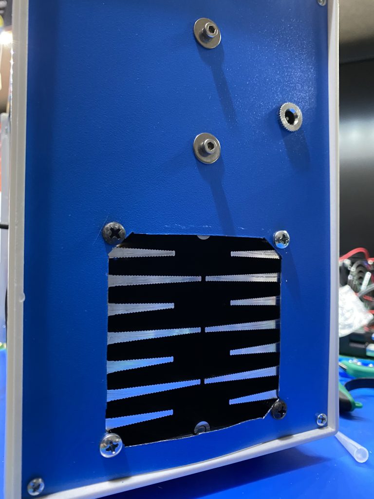
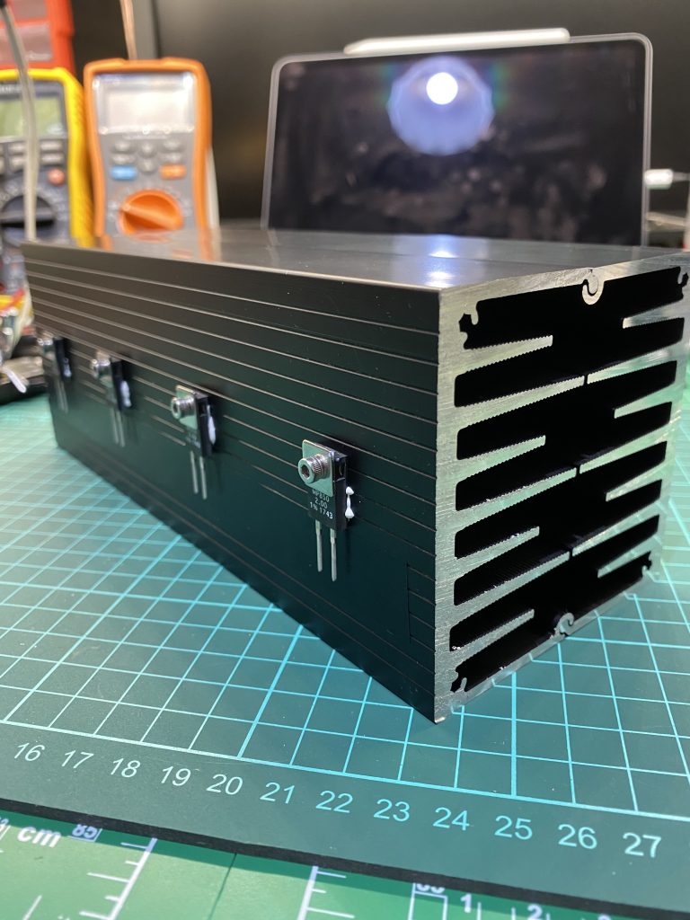
Above is the back of the unit, I used a nibbler to cut out the rear for the heatsink to bolt on and let out all the heat, as I was going to flow the fan from inside to out. No need to make any holes at the front as the Fan will suck the air in from the vented case sides, they are vented.
The Front above now looks like this, Yes the switches are a bit close, but I was running out of space as the HeatSink took up a lot of the front space. To make it a bit safer I used a Lift and switch DPDT Resistance switch from Altronics. S1348 • DPDT With Locking Mech. Solder Tail Mini Toggle Switch Link below:

https://www.altronics.com.au/p/s1348-salecom-dpdt-with-locking-mech.-solder-tail-mini-toggle-switch/
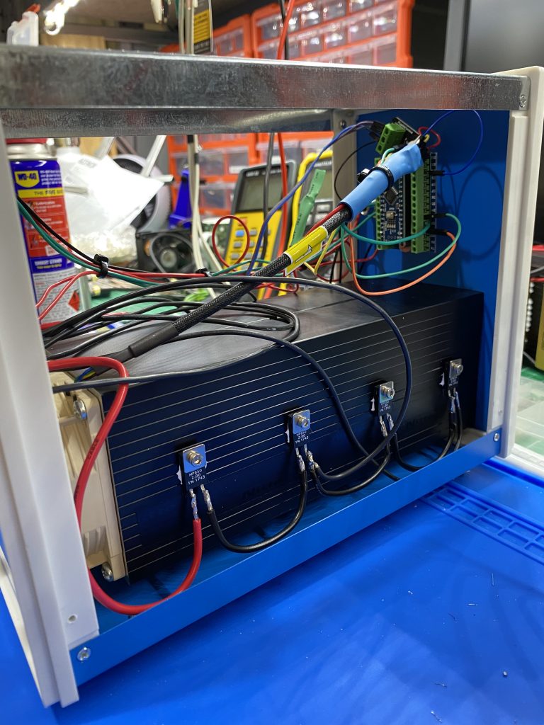
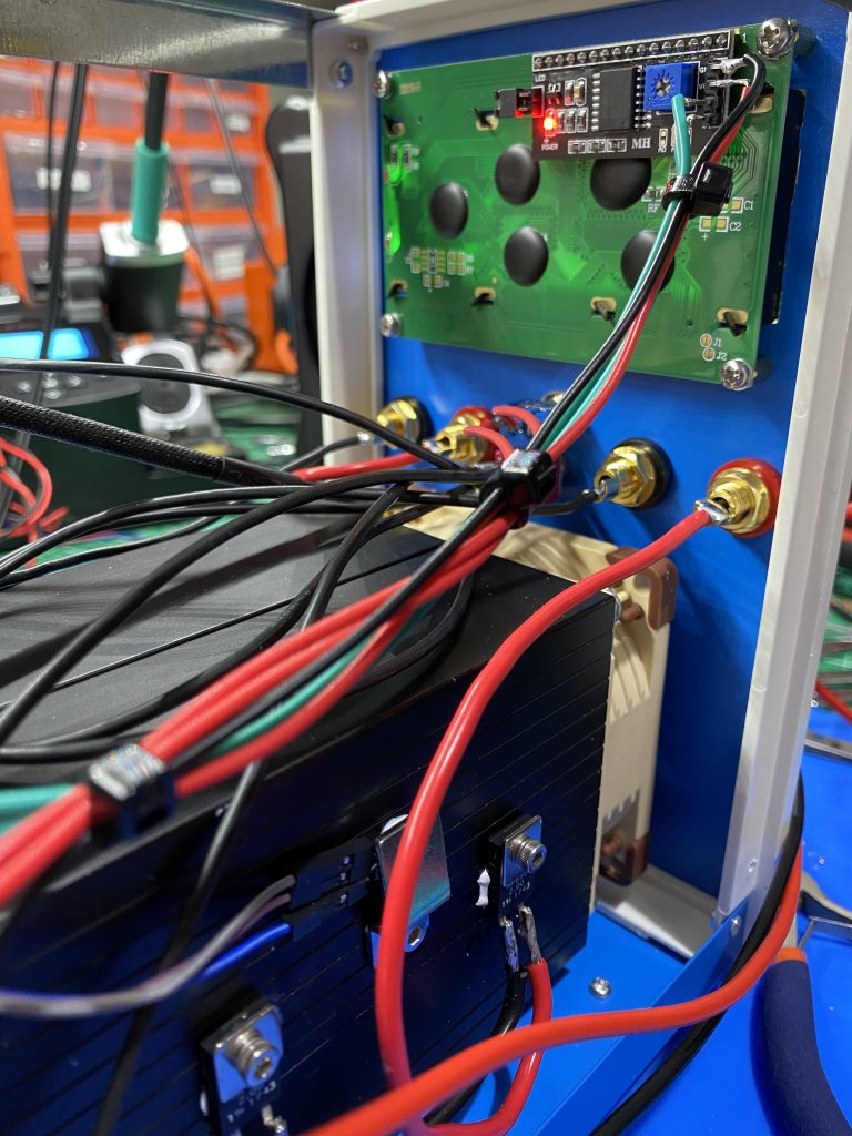
Finished mounting the rear Nano and finished all the wiring, now time to just temporarily power it up and see if the Fan and LCD work etc.

Ran the PSU into the Dummy load to check the Fan operation, once it hit 50Deg the fan was running at full speed and kept the load cool around ~53Deg.
Very happy with the finished product, onto my workbench it goes.